Product Description
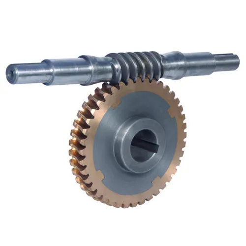
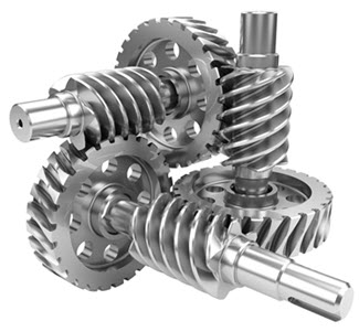
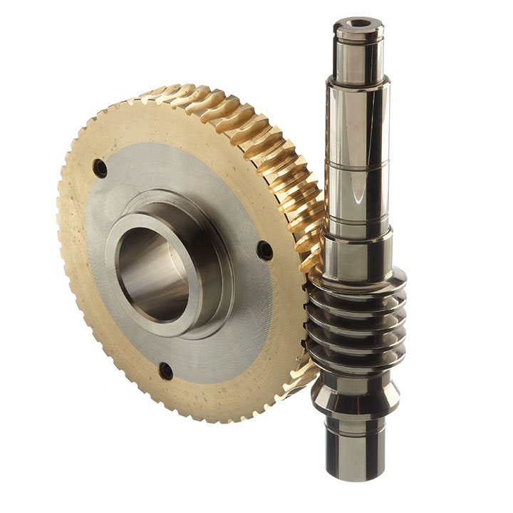
Silicone Rubber Plastic Injection Moulding Worm Gear
Our service
We provide comprehensive turn-key solution based on our indutry clients needs
which including:product design,prototyping,mold making,mass production,assembly,
packing and shipping service.
| Product Name | Plastic Injection Molding | ||
| Material | PP/PE/PS/ABS/PA/PA with GF/POM | ||
| Color | Customize | ||
| Standard | ISO9001:2015 | ||
| Mould material | P20/718/738/NAK80/S136 | ||
| Mould base | LKM Mould Base | ||
| ription | ODM plastic injection molding | ||
| Plastic Materials: | PS, ABS, PP, PVC, PBT, PC, POM, PA66, PA6, PBT+GF, PC/ABS, PEEK, HDPE, TPU, PET, PPO,…etc. | ||
| Standard: | ISO9001:2015 | ||
| Other materials: | Rubber, Slilconce rubber, LSR,Aluminum, Zinc,Copper…Metal…etc. | ||
| Quality: | RoSH and SGS standard | ||
| Feature: | Non marking and Non flash | ||
| Size: | According to your 2D, 3D Drawing | ||
| Color,Quantity,Unit price,Tooling cost,Tooling size: | To be discussed | ||
| Package: | Standard exported Wooden box packed, Fumigation process(upon required) | ||
| Mold Building Lead Time: | T1, 4-5 weeks, Part measurement report (upon required). | ||
| Export Country: | Europe, Japan, America, Australian, UK, Canada, France, Germany, Italy…etc.: | ||
| Experience: | 13 years experience in plastic injection mold making and plastic prouducts produce. | ||
| To be discussed | In-Mold Decoration, Injection Mould, Plastic Mold, Overmould, 2K Mould, Die-Casting Mould, Thermoset Mold, Stack Mold, Interchangeable Mold,Collapsible Core Mold, Die Sets, Compression Mold, Cold Runner System LSR Mold,…etc. | ||
| Mould Base: | Hasco Standard, European Standard, World Standard | ||
| Mould Base Material: | LKM, FUTA, HASCO, DME,…etc. Or as per Customer’s Requirment. | ||
| Surface Finish: | Texture(MT standard), High gloss polishing | ||
| Cavity/Core Steel: | P20, 2311, H13, 2344, Starvax 420, 236, AdC3, S136, 2312, 2379, 2316, 2083, Nak80, 2767 …etc. | ||
| Hot/ Cold Runner | HUSKY, INCOE, YDDO, HASCO, DME, MoldMaster, Masterflow, Mastip, ZheJiang made brand…etc. | ||
| Mould Life: | 5,000 to 1,000,000 Shots. (According to your working environment.) | ||
| Design & Program Softwares: | CAD, CAM, CAE, Pro-E, UG, Soild works, Moldflow, CATIA….etc. | ||
| Equipments: | High speed CNC, Standard CNC, EDM, Wire Cutting, WEDM, Grinder, Plastic Injection Molding Machine for trial out mold from 50-3000T available. | ||
| Product Type | Plastic Injection | ||
| Our Services | CNC Machining,Plastic Injection,Stamping,Die Casting,Silicone And Rubber,Aluminum Extrusion,Mould Making,etc | ||
| Material | Aluminum,Brass,Stainless Steel,Copper,Plastic,Wood,Silicone,Rubber,,Or as per the customers’ requirements | ||
| Surface Treatment | Anodizing,Sandblasting,Painting,Powder coating,Plating,Silk Printing,Brushing,Polishing,Laser Engraving | ||
| Drawing Format | .jpg/.pdf/.dxf/.dwg/.igs./.stp/x_t. etc | ||
| Service Project | To provide production design, production and technical service, mould development and processing, etc | ||
| Testing Machine | Digital Height Gauge, caliper, Coordinate measuring machine, projection machine, roughness tester, hardness tester and so on | ||
| Packing | Foam, Carton, Wooden boxes, or as per the customer’s requirements | ||
| Payment Terms | T/T,Western Union,Paypal | ||
Quality assurance
We have digital altimeters, calipers, coordinate measuring machines, projectors, roughness
testers, hardness testers, etc. to escort your quality.
We provide you with consumable parts for free.
Mold product details
| Mould Type | China Top Tool Maker MIM injection Multi-Cavity Moulding Mold |
| Design Software | UG, ProE, Auto CAD, Solidworks, etc. |
| Mould Material | 718H, P20, NAK80, S316H, SKD61, etc. |
| Hardness of the steel | 20~60 HRC |
| Mould Base | HASCO, DME, LKM, etc. |
| Runner | Hot runner, Cold runner, as per customers requirement and part structure. |
| Mould Cavity | Single-cavity or Multi-cavit, as per customers requirement and part structure. |
| Ejection Techniques | Pin ejection, sleeve ejection, bar ejection, blade ejection, etc. |
| Gate Type | Edge gate, sub-gate, pin gate, side gate, etc. |
| Mould hot treatment | Quencher, Nitridation, Tempering, etc. |
| Mould Cooling System | Water cooling or Beryllium bronze cooling, etc. |
| Mould Surface | EDM, texture, high gloss polishing |
| Mould Life | >500,000 shots |
| Equipments | High speed CNC, standard CNC, EDM, Wire cutting, Grinder, Lathe, Milling machine, plastic injection machine |
| Raw material of metal injection | 316L,17-4ph,420,440c,al203,zr02,si02,fe,ndfeb,smco5,fe-si,wc-co,fe-2ni,fe-8ni,ti,ti-6al-4v, etc. |
| Lead time | 25~60 days |
1. Q: Why choose Jufeng product?
A: We CHINAMFG have our own plant– HangZhou CHINAMFG machinery Co., Ltd, therefore,
we can surely promise the quality of every product and provide you comparable price.
2. Q: Do you provide OEM Service?
A: Yes, we provide OEM Service.
3. Q: Do you provide customized plastic products?
A: Yes. Customers give us drawings and specifications, and we will manufacture accordingly.
4. Q: What is your payment term?
A: We provide kinds of payment terms such as L/C, T/T, Paypal, Escrow, etc.
If there’s anything we can help, please feel free to contact with us.
|
Shipping Cost:
Estimated freight per unit. |
To be negotiated |
|---|
| Material: | ABS |
|---|---|
| Application: | Medical, Household, Electronics, Automotive, Agricultural |
| Certification: | RoHS, ISO |
| Samples: |
US$ 1/Piece
1 Piece(Min.Order) | Order Sample plastic gear
|
|---|
| Customization: |
Available
| Customized Request |
|---|

How do you prevent backlash and gear play in a worm gear mechanism?
Preventing backlash and gear play is essential for maintaining the accuracy and performance of a worm gear mechanism. Here’s a detailed explanation of how to prevent backlash and gear play in a worm gear mechanism:
Backlash refers to the play or clearance between the teeth of the worm and the worm wheel in a worm gear mechanism. It can result in inaccuracies, positioning errors, and reduced efficiency. Here are some measures to prevent or minimize backlash and gear play:
- Precision manufacturing: Accurate and precise manufacturing of the worm and worm wheel is crucial to minimize backlash. High-quality machining techniques, such as grinding, can be employed to achieve precise tooth profiles and minimize any gaps between the teeth. Careful attention to the design and manufacturing tolerances can help reduce backlash.
- Tight meshing clearance: Proper adjustment of the meshing clearance between the worm and the worm wheel can help minimize backlash. The meshing clearance should be set as small as possible without causing interference or excessive friction. Close clearance ensures a tighter fit between the teeth, reducing the amount of play or backlash.
- Anti-backlash mechanisms: Anti-backlash mechanisms can be incorporated into the worm gear system to reduce or eliminate backlash. These mechanisms typically consist of spring-loaded components or adjustable devices that help compensate for any clearance between the teeth. They apply a constant pressure to keep the teeth engaged tightly, reducing the effects of backlash.
- Preload: Applying a preload to the worm gear system can help minimize backlash. Preload involves applying a slight compressive force or tension to the components, ensuring they remain engaged and eliminating any clearance. However, it is important to apply the appropriate preload to avoid excessive friction and wear.
- Lubrication: Proper lubrication is crucial for minimizing backlash and reducing gear play. Lubricants with suitable viscosity and properties should be used to ensure smooth and consistent operation of the worm gear mechanism. Good lubrication helps reduce friction, wear, and any potential clearance that can contribute to backlash.
- Regular maintenance: Regular inspection and maintenance of the worm gear mechanism can help detect and address any developing backlash or gear play. Routine checks can identify signs of wear, misalignment, or improper lubrication, allowing for timely adjustments or replacements to minimize backlash and maintain optimal performance.
It’s important to note that completely eliminating backlash in a worm gear mechanism may not always be possible or desirable. Some applications require a certain level of backlash to accommodate thermal expansion, compensate for positional errors, or allow for smooth operation. The acceptable level of backlash depends on the specific requirements of the application.
When implementing measures to prevent backlash and gear play, it is crucial to strike a balance between minimizing backlash and ensuring smooth, reliable operation. The specific techniques and approaches used to minimize backlash may vary depending on the design, manufacturing, and application requirements of the worm gear mechanism.

How do you ensure proper alignment when connecting a worm gear?
Ensuring proper alignment when connecting a worm gear is crucial for the smooth and efficient operation of the gear system. Here’s a detailed explanation of the steps involved in achieving proper alignment:
- Pre-alignment preparation: Before connecting the worm gear, it is essential to prepare the components for alignment. This includes cleaning the mating surfaces of the gear and shaft, removing any debris or contaminants, and inspecting for any signs of damage or wear that could affect the alignment process.
- Measurement and analysis: Accurate measurement and analysis of the gear and shaft alignment are essential for achieving proper alignment. This typically involves using precision alignment tools such as dial indicators, laser alignment systems, or optical alignment instruments. These tools help measure the relative positions and angles of the gear and shaft and identify any misalignment.
- Adjustment of mounting surfaces: Based on the measurement results, adjustments may be required to align the mounting surfaces of the gear and shaft. This can involve shimming or machining the mounting surfaces to achieve the desired alignment. Care should be taken to ensure that the adjustments are made evenly and symmetrically to maintain the integrity of the gear system.
- Alignment correction: Once the mounting surfaces are prepared, the gear and shaft can be connected. During this process, it is important to carefully align the gear and shaft to minimize misalignment. This can be done by observing the alignment readings and making incremental adjustments as necessary. The specific adjustment method may vary depending on the type of coupling used to connect the gear and shaft (e.g., keyway, spline, or flange coupling).
- Verification and final adjustment: After connecting the gear and shaft, it is crucial to verify the alignment once again. This involves re-measuring the alignment using the alignment tools to ensure that the desired alignment specifications have been achieved. If any deviations are detected, final adjustments can be made to fine-tune the alignment until the desired readings are obtained.
- Secure fastening: Once the proper alignment is achieved, the gear and shaft should be securely fastened using appropriate fasteners and tightening procedures. It is important to follow the manufacturer’s recommendations for torque values and tightening sequences to ensure proper clamping force and prevent any loosening or slippage.
It is worth noting that the alignment process may vary depending on the specific gear system, coupling type, and alignment tools available. Additionally, it is important to refer to the manufacturer’s guidelines and specifications for the particular gear and coupling being used, as they may provide specific instructions or requirements for alignment.
Proper alignment should not be considered a one-time task but an ongoing maintenance practice. Regular inspections and realignment checks should be performed periodically or whenever there are indications of misalignment, such as abnormal noise, vibration, or accelerated wear. By ensuring proper alignment during the initial connection and maintaining it throughout the gear’s operational life, the gear system can operate optimally, minimize wear, and extend its service life.

How do you calculate the gear ratio of a worm gear?
Calculating the gear ratio of a worm gear involves determining the number of teeth on the worm wheel and the pitch diameter of both the worm and worm wheel. Here’s the step-by-step process:
- Determine the number of teeth on the worm wheel (Zworm wheel). This information can usually be obtained from the gear specifications or by physically counting the teeth.
- Measure or determine the pitch diameter of the worm (Dworm) and the worm wheel (Dworm wheel). The pitch diameter is the diameter of the reference circle that corresponds to the pitch of the gear. It can be measured directly or calculated using the formula: Dpitch = (Z / P), where Z is the number of teeth and P is the circular pitch (the distance between corresponding points on adjacent teeth).
- Calculate the gear ratio (GR) using the following formula: GR = (Zworm wheel / Zworm) * (Dworm wheel / Dworm).
The gear ratio represents the speed reduction and torque multiplication provided by the worm gear system. A higher gear ratio indicates a greater reduction in speed and higher torque output, while a lower gear ratio results in less speed reduction and lower torque output.
It’s worth noting that in worm gear systems, the gear ratio is also influenced by the helix angle and lead angle of the worm. These angles determine the rate of rotation and axial movement per revolution of the worm. Therefore, when selecting a worm gear, it’s important to consider not only the gear ratio but also the specific design parameters and performance characteristics of the worm and worm wheel.


editor by CX 2023-10-04